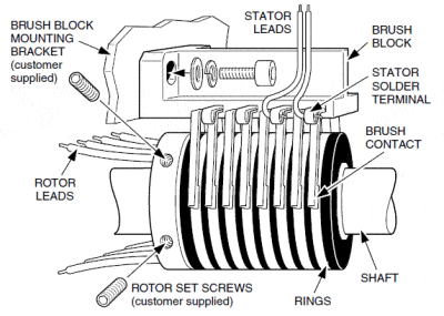
.50 & 2.00 Inch Diameter Thru Bore
(Catalog Pages 1 & 4 – Aluminum Rotor Structure)
- Rigidly mount rotor to shaft using rotor set screws.
- Align brush block on rotor and push radially into position. Do not slide brush block axially across rotor.
- Secure brush block to mounting bracket.
- Verfiy proper alignment of brush contacts on rings.
- If required, remove brush block and adjust axial position of brush block mounting bracket or rotor to center brush contacts on rings.
- Solder stator leads to stator solder terminals.
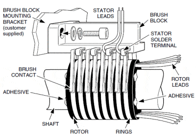
1.00 & 1.50 Inch Diameter Thru Bore
(Catalog Pages 2 & 3 – No Aluminum Rotor Structure)
- Rigidly mount rotor to shaft using appropriate adhesive (epoxy, Locktite®, etc.), or mechanical method (collar, wave ring, etc.).
- Align brush block on rotor and push radially into position. Do not slide brush block axially across rotor.
- Secure brush block to mounting bracket.
- Verify proper alignment of brush contacts on rings.
- If required, remove brush block and adjust axial position of brush block mounting bracket to center brush contacts on rings.
- Solder stator leads to stator solder terminals.
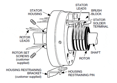
Rotor Rigid / Housing Floating
(Catalog Pages 5, 6, 7, and 8)
- Rigidly mount rotor to shaft using rotor set screws.
- Secure housing restraining pin with the housing restraining bracket (customer supplied).
- Allow housing restraining pin to float in housing restraining bracket.
- Wire stator.
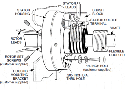
Housing Rigid / Rotor Floating
(Catalog Pages 5, 6, 7, and 8)
- Secure slip ring housing to mounting bracket. 1/4-inch bolts can be inserted through .265 inch diameter thru holes.
- Attach rotor using some type of flexible coupling method (customer supplied).
- Wire stator.


